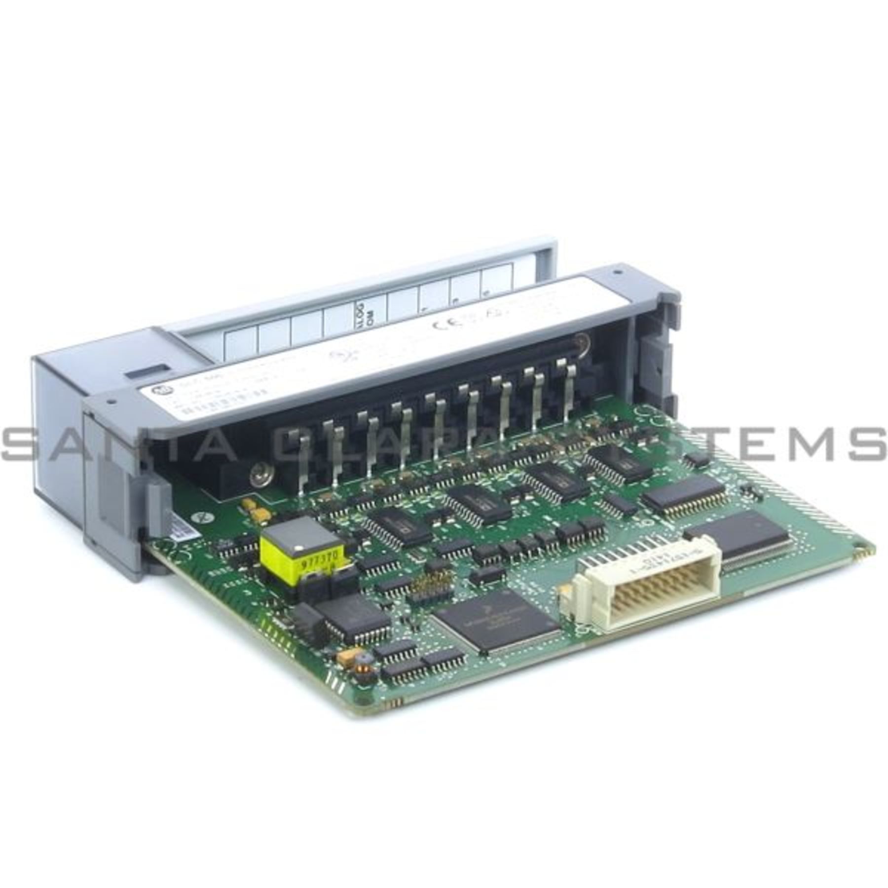
- Analog Input Module
- Slc 500 Analog Input Module User Manual
- Analog Module Inc
- Types Of Analog Inputs
- Analog Inputs And Outputs
4–2
SLC 500 Thermocouple/mV Analog Input Module 1746-NT8 User Manual. Important User Information Solid state equipment has operational characteristics differing from those of electromechanical equipment. View and Download Allen-Bradley SLC 500 user manual online. SLC 500 Modular Hardware Style. SLC 500 Controller pdf manual download. Thermocouple/mv analog input module (110 pages) I/O Systems Allen-Bradley SLC 500 User Manual. Thermocouple/mv analog input module (91 pages) I/O Systems Allen-Bradley SLC 500 Installation Instructions Manual. Attention statements help you to:.identify a hazard.avoid the hazard.recognize the consequencesImportant: Identifies information that is critical for.
Preliminary Operating Considerations
Publication 1746Ć6.8 - April 1997
The 1746-NI8 analog input module has multiclass interface
capabilities. Class 1 is the standard configuration. The module can
be configured through the user program for Class 3 which enables
user-defined data scaling and monitoring of channel status words.
Configuration
Class 1
Class 3
Compatible SLC
Processors
SLC 500 fixed, SLC 5/01, SLC 5/02,
SLC 5/03, and SLC 5/04
SLC 5/02, SLC 5/03, and SLC 5/04
Compatible

Chassis
local chassis or remote chassis with a
1747ĆASB module
local chassis
Input and
Output Images
output image:
8 channel configuration words
input image:
8 channel data words
output image:
8 channel configuration words and 4 limit ranges
for userĆdefined scaling data format
input image:
8 channel data words and 8 channel status words
Default
Class 1 is the default on powerĆup
Class 3 is programmable by user
The following memory maps show you how the input and output
input image tables are defined for Class 1 and Class 3.
Class 1 Memory Map
Channel 0 Configuration Word
Channel 1 Configuration Word
Channel 2 Configuration Word
Channel 3 Configuration Word
Channel 0 Data Word
Channel 1 Data Word
Channel 2 Data Word
Channel 3 Data Word
Channel 4 Data Word
Channel 5 Data Word
Channel 6 Data Word
Channel 7 Data Word
Output Image
8 Words
Input Image
8 Words
Output Image
Input Image
Output
Scan
Input
Scan
Output Image
Input Image
Slot e
Slot e
SLC 5/0X
Data Files
Analog Input
Module
Image Table
Bit 15
Bit 0
Bit 15
Bit 0
Word 0
Word 1
Word 2
Word 3
Word 7
.
.
.
.
.
.
Word 0
Word 1
Word 2
Word 3
Word 4
Word 5
Word 6
Word 7
Address
Analog Input Module
Address
O:e.0
O:e.1
O:e.2
O:e.3
O:e.7

I:e.0
I:e.1
I:e.2
I:e.3
I:e.4
I:e.5
I:e.6
I:e.7
(Class 1)
Channel 4 Configuration Word
Channel 5 Configuration Word
Channel 6 Configuration Word
Channel 7 Configuration Word
Slc 500 Analog Input Module User Manual
Class 1 and Class 3
Analog Module Inc
Interface

Module Addressing